Karlsson Robotics
MMA7361LC 3-Axis Accelerometer +-1.5/6g with Voltage Regulator
MMA7361LC 3-Axis Accelerometer +-1.5/6g with Voltage Regulator
Couldn't load pickup availability
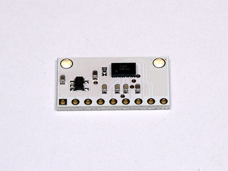
This three-axis accelerometer is a breakout board for Freescale's MMA7361L (175k pdf) and MMA7341L (175k pdf) MEMS (micro-electro-mechanical systems) low-g accelerometers; we therefore recommend careful reading the appropriate datasheet for your particular carrier board before using this product. The MMA7361 and MMA7341 are great ICs, but their small, leadless packages makes them difficult for the typical student or hobbyist to use. This carrier board includes all of the components in the part's recommended connection diagram and includes a 3.3V 50mA ultra-low-dropout linear voltage regulator, which allows the accelerometer breakout board to accept a wide range of input voltages (2.2-16 V) with power to spare for additional 3.3V components. The accelerometer s pins are 0.1 spaced to work well with standard solderless breadboards and 0.1 perfboards.
Specifications
- Dimensions: 0.5 x 0.9 x 0.09 (1.2 2.3 0.23 cm) (without header pins)
- Operating voltage: 2.2-16 V connected to VIN (all pins besides VIN are not 5V-tolerant)
- Supply current: 0.5 mA
- Output format: 3 analog voltages (one signal for each axis) centered at half the voltage of the 3V3 pin
- Sensitivity range (selectable using g-Select pin):
- MMA7361L version: +-1.5g (default) or +-6g
- MMA7341L version: +-3g (default) or +-11g
- Weight without header pins: 0.025 oz (0.7 g)
Using the sensor
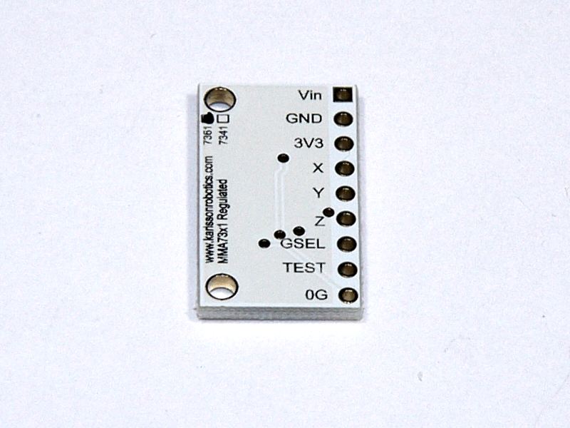
To power the three-axis accelerometer, connect 2.2-16 V battery or power supply to the VIN pin. Note that this part does not have 5V-tolerant pins, so external components (such as voltage dividers) are required when interfacing the board s g-Select and Self Test pins with 5V systems. Connections to the g-Select and Self Test pins are optional; the board will work with these pins disconnected.
The accelerometer X, Y, and Z outputs are three separate analog voltages centered at half the voltage of the 3V3 pin. Positive accelerations along an axis increase that axis\\ s output voltage above the center voltage and negative accelerations decrease the output voltage below the center voltage. The outputs will always be within the range of 0 to the voltage of the 3V3 pin.
The sensitivity selection pin, g-Select, is internally pulled low, which selects for a default sensitivity of �1.5g (800 mV/g) on the MMA7361L carrier and �3g (440 mV/g) on the MMA7341L carrier. Driving the pin high selects for a sensitivity of �6g (206 mV/g) on the MMA7361L carrier and �11g (118 mV/g) on the MMA7341L carrier.
The 0g-Detect pin outputs high when all three axes simultaneously detect 0g, which happens when the board is in free-fall. This pin is only documented in the datasheet of the more sensitive MMA7361L IC (the MMA7341L datasheet labels this pin as NC), but we have found that it works on the MMA7341L at its default �3g sensitivity. This output does not work at the �11g sensitivity setting.
The Self Test pin is pulled low on the board and can be left disconnected.
For very low power applications, the three-axis accelerometer can be powered by a 2.2-3.6V IO pin connected to 3V3. This lets you bypass the regulator avoiding its small current draw and allows the microcontroller to control power to the board and turn it off when not in use. For applications where a voltage regulator is not needed, we sell smaller versions of this carrier board: the MMA7361L 3-axis accelerometer carrier, and the MMA7341L 3-axis accelerometer carrier.
Included components
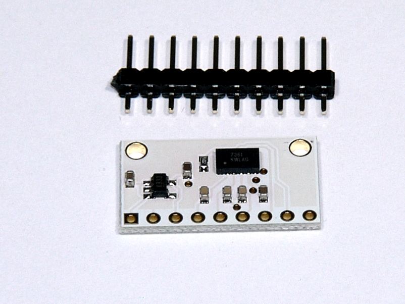
A 10 strip of 0.1 header pins.